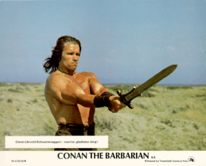
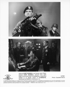
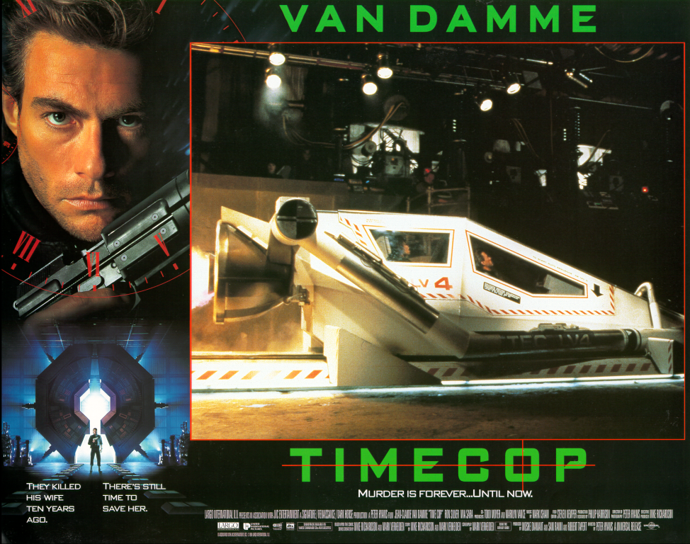
The classic Arnold Schwarzenegger movie.
The classic Arnold Schwarzenegger movie.
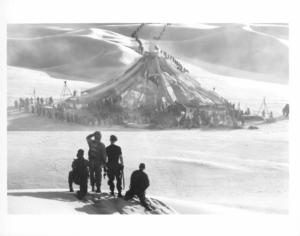
The original Stargate from 1994 was pretty good movie. I remember watching most of these movies at a friends house, he had a nice collection of laserdiscs, a three beam CRT projector and a cool sound system.
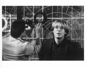
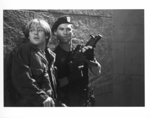
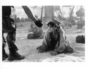
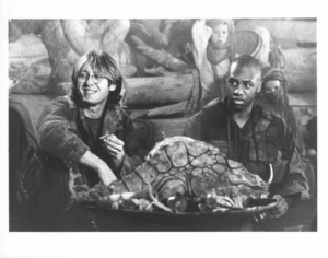
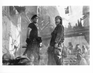
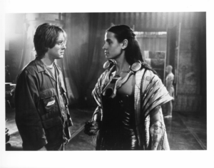

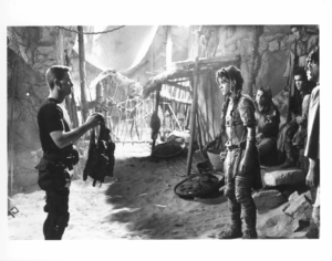
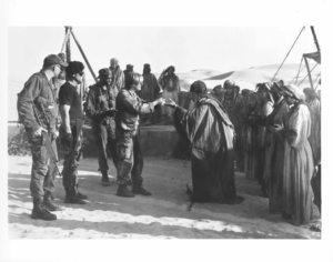
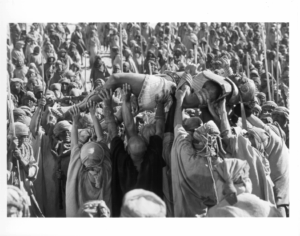
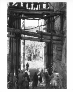
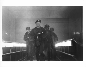
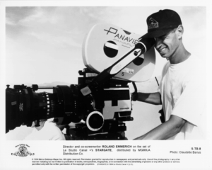

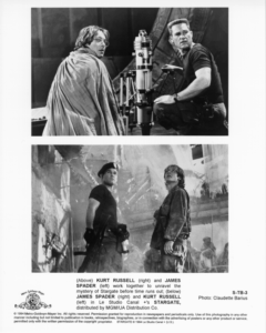
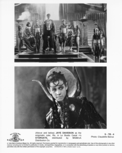
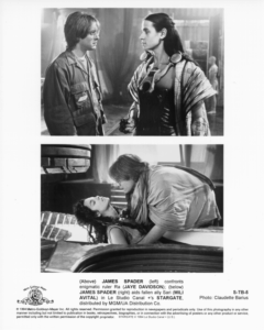
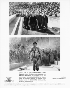
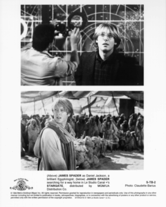
I found an old collection of movie stills that I scanned from the original “still sets” perhaps 20 or so years ago. Unfortunately the image resolution is not ideal as disk space was expensive back in the day. I remember the A3 SCSI scanner I used, must have cost a fortune. I’m also surprised the CD was still readable. I still have a few of the original sets so perhaps I’ll rescan with some modern equipment, someone may be interested.
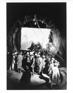
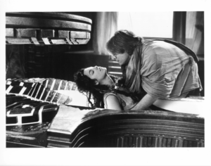
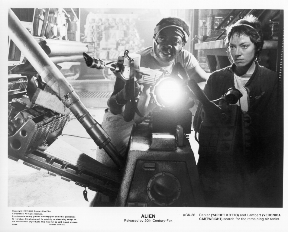
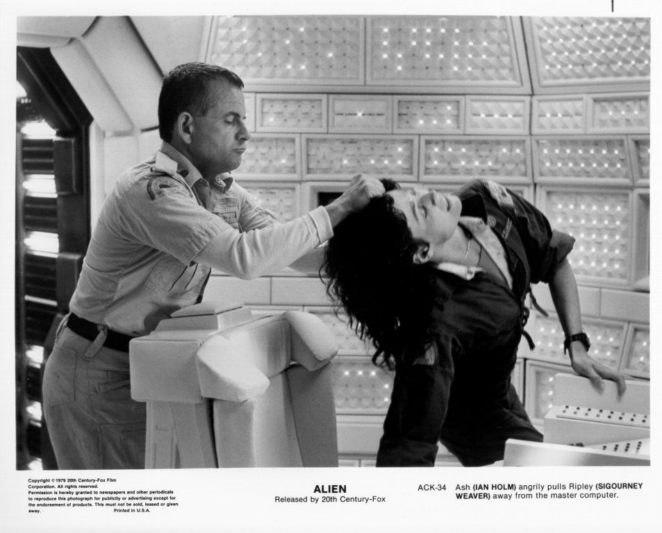
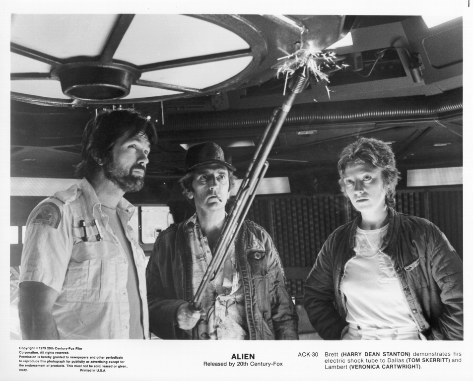
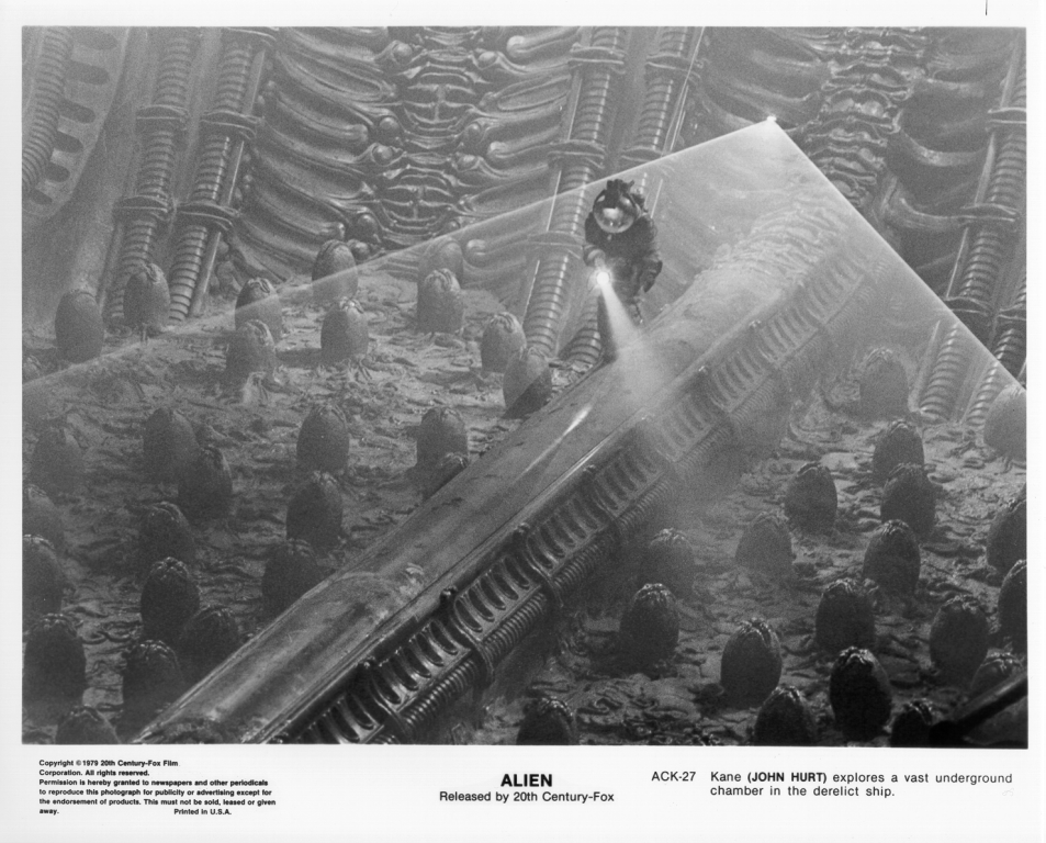
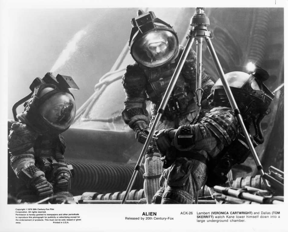
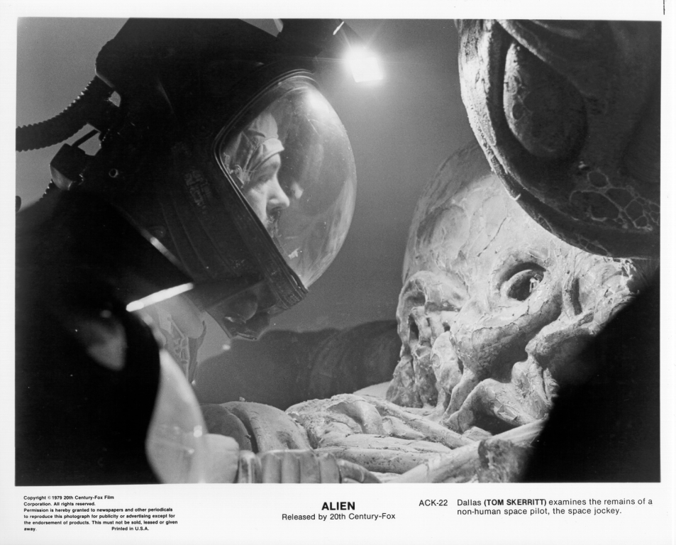
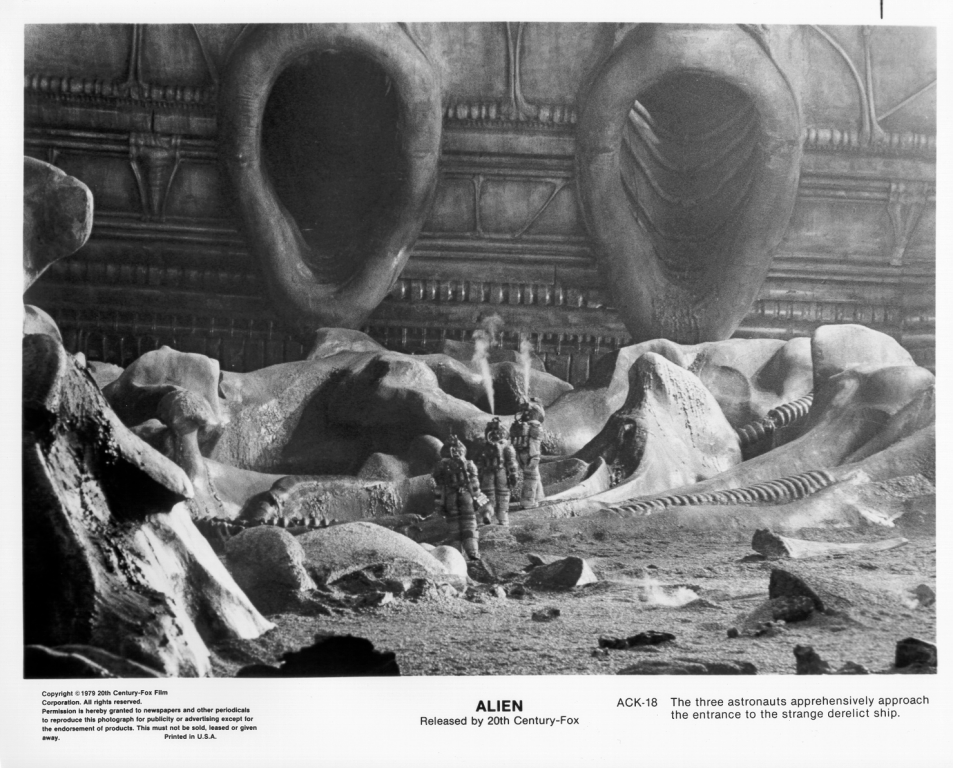
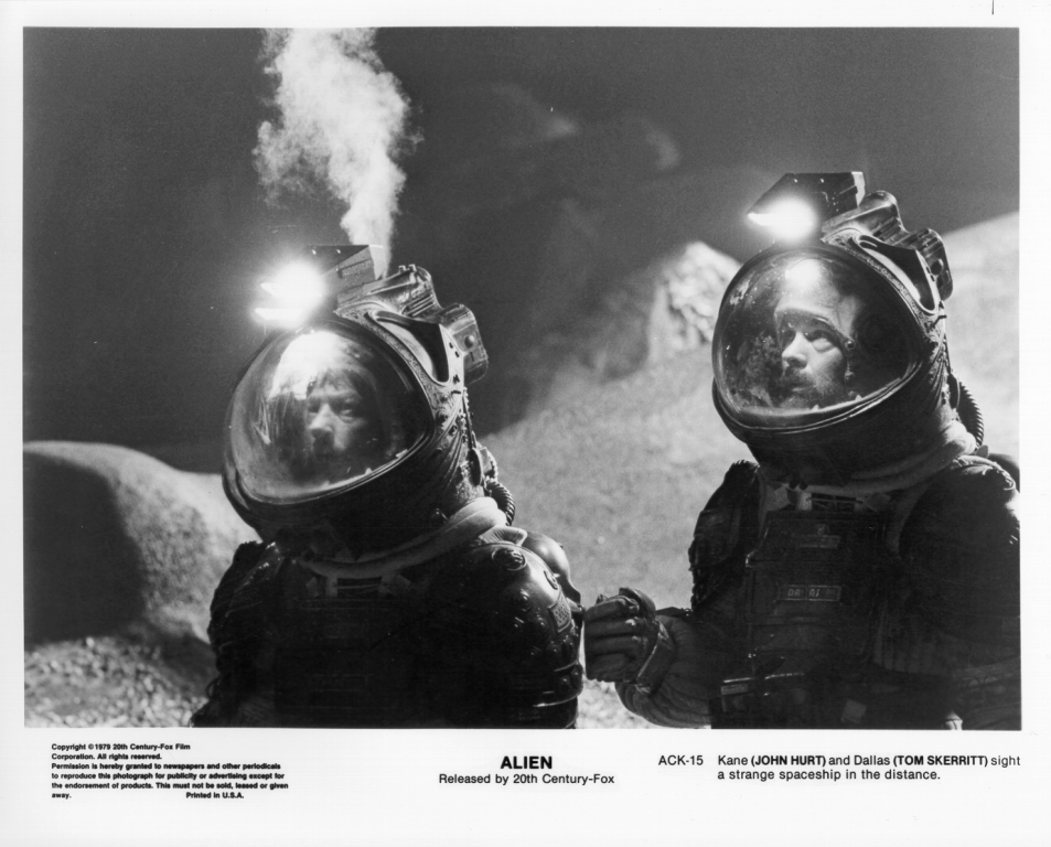
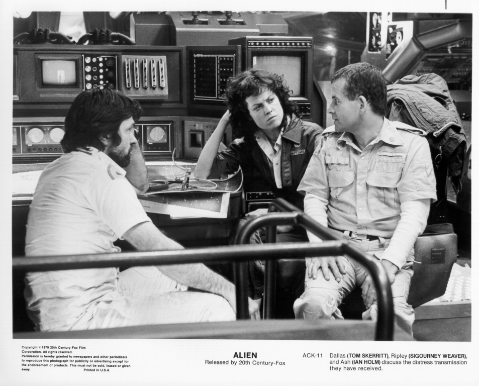
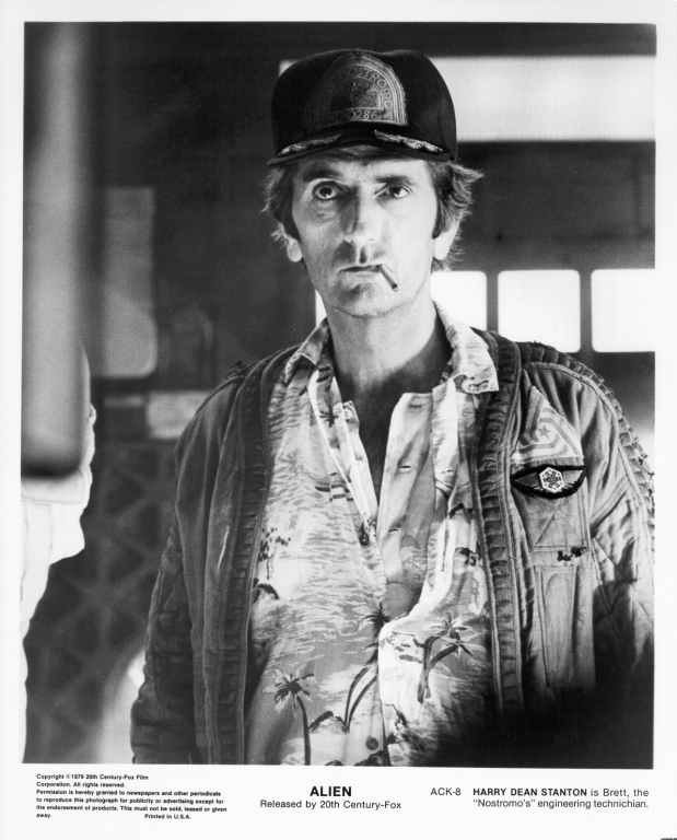
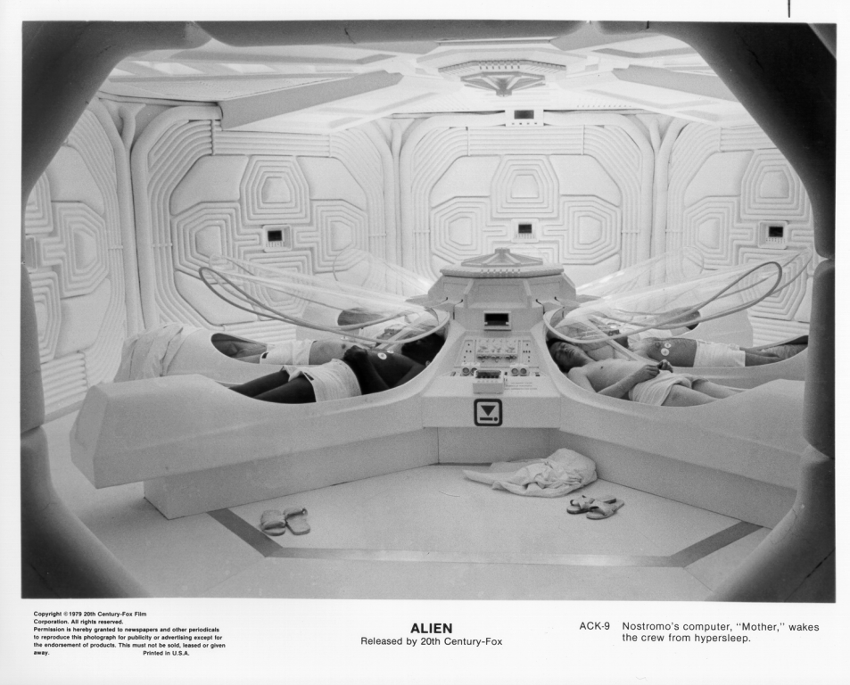
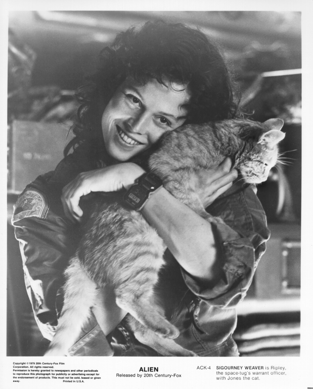
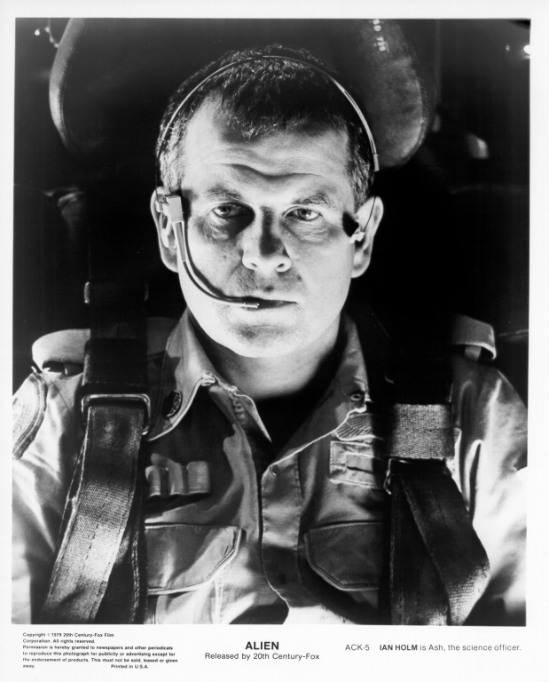
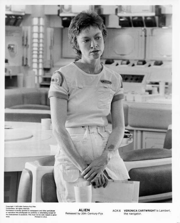
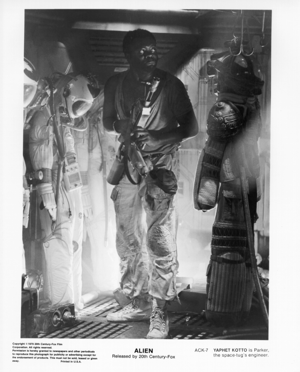
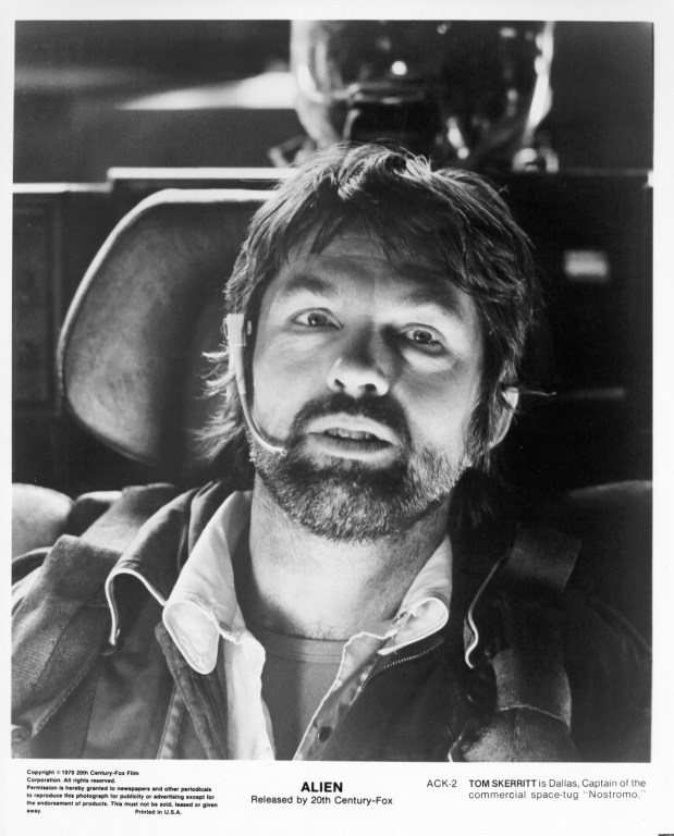
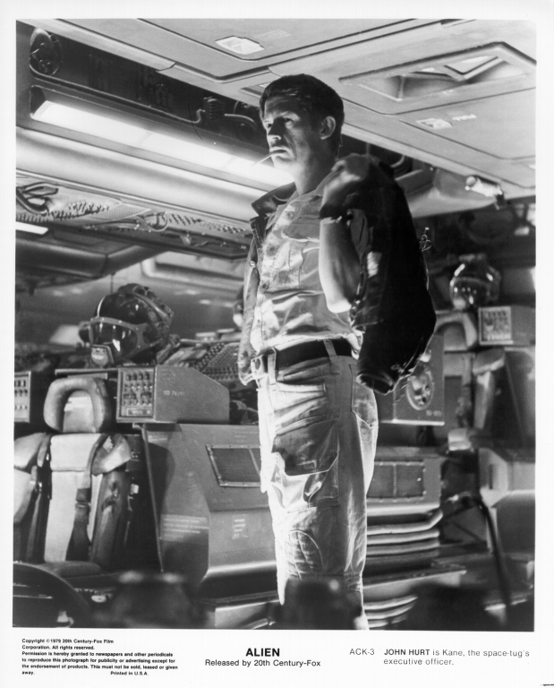
I start with the classic Alien from 1979. There are color versions elsewhere on the internet but these particular ones were black and white.
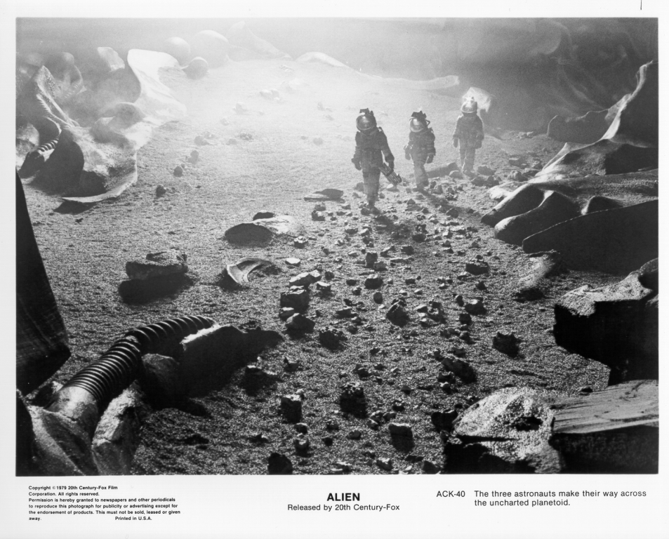
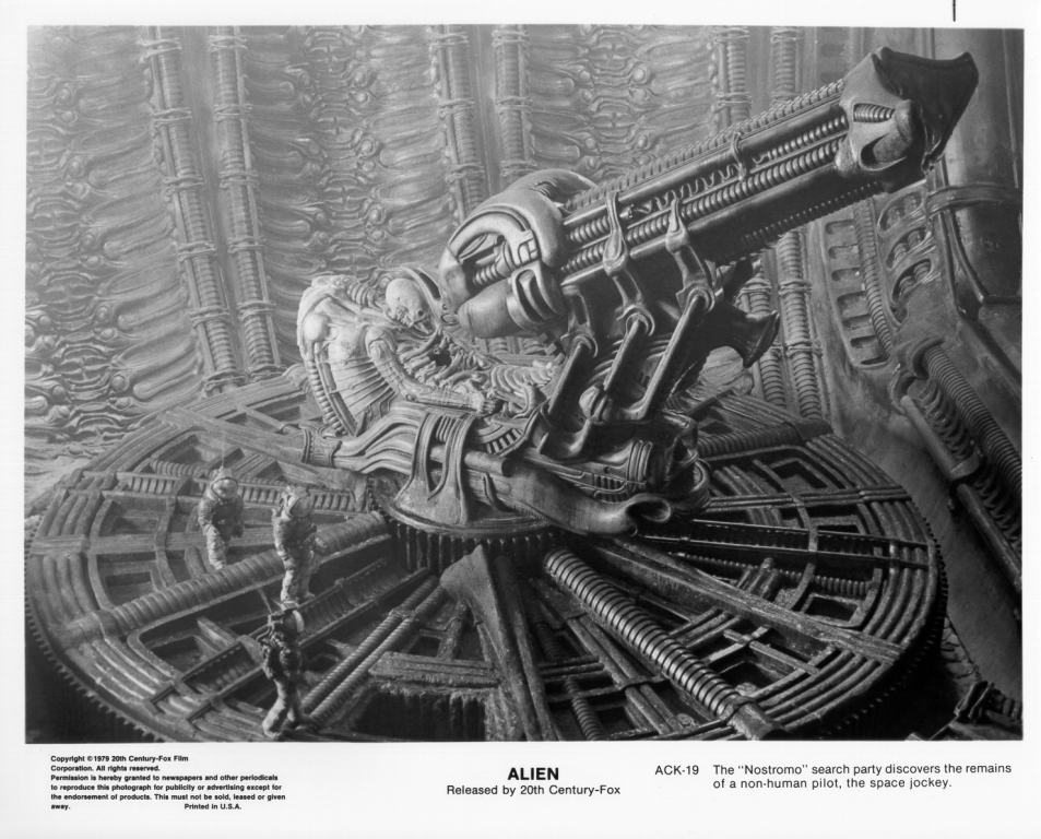
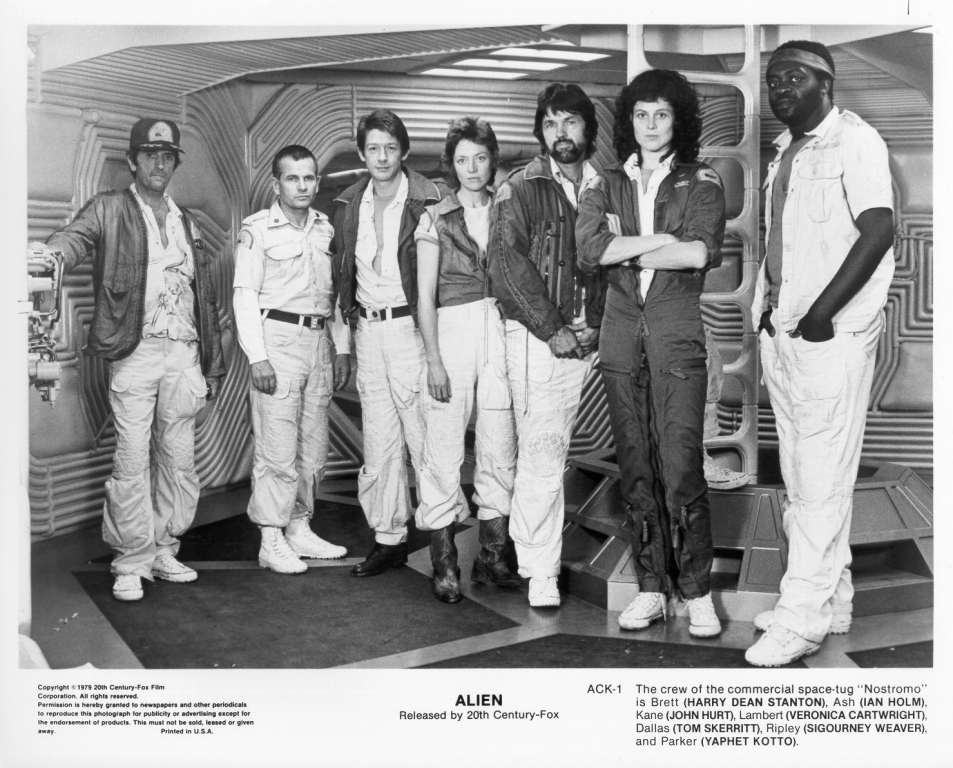
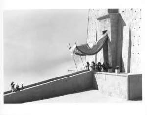
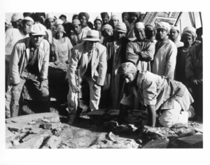
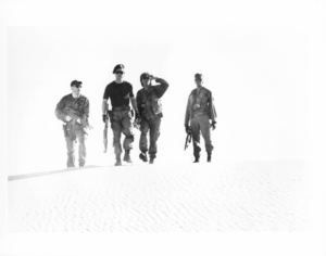
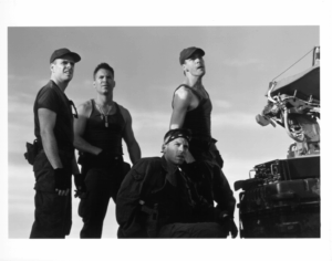
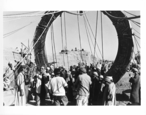
You can see the rear end of the prototype Cybertruck in one image.
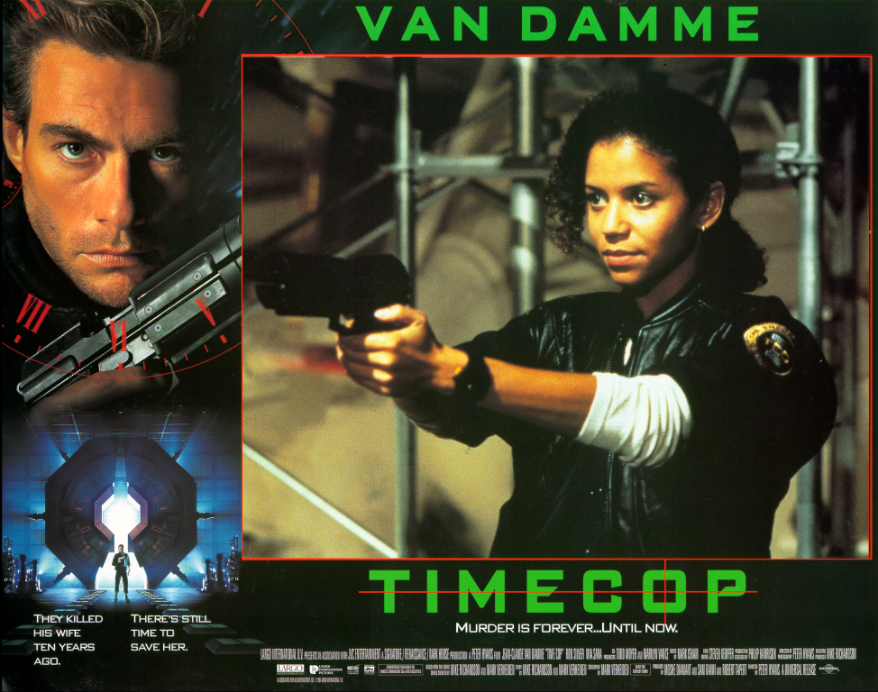
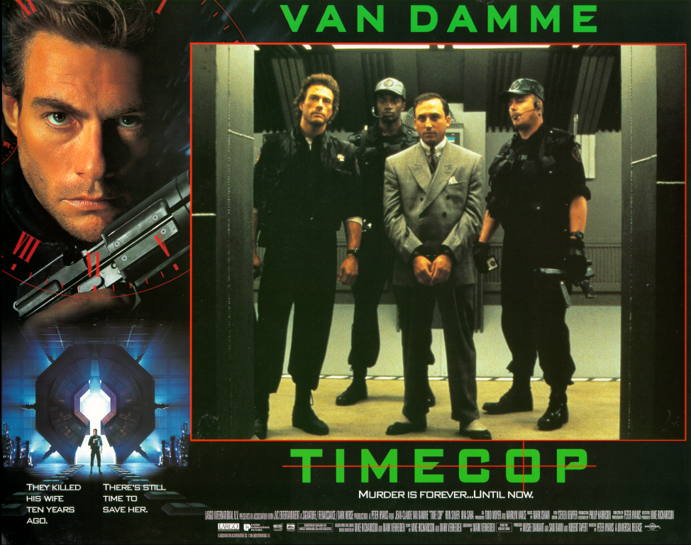
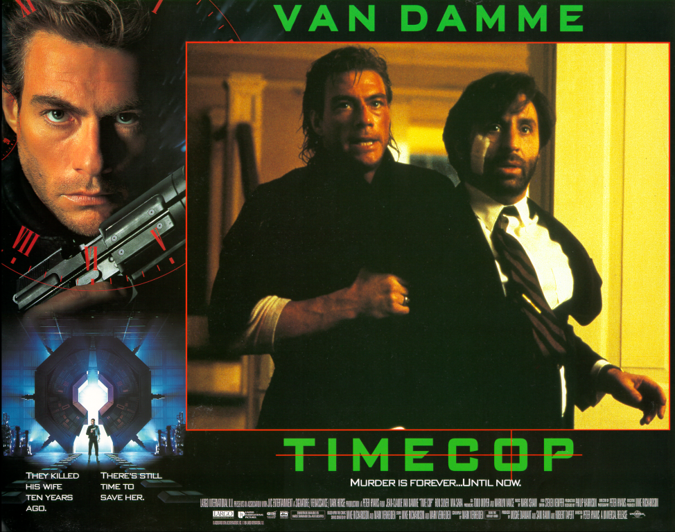
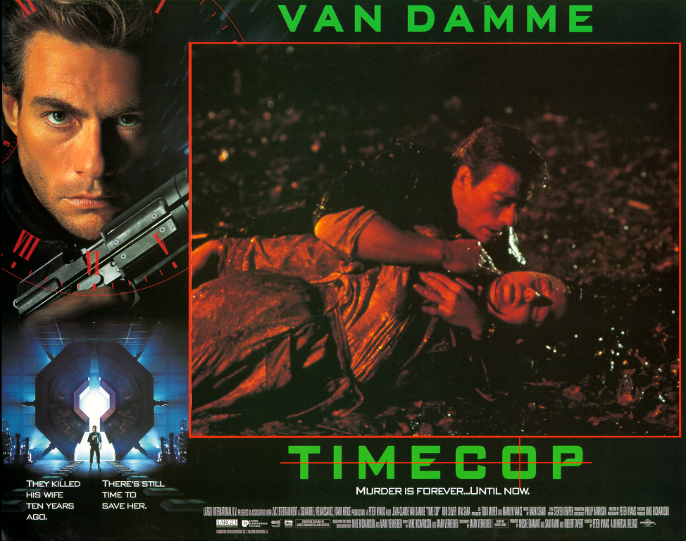
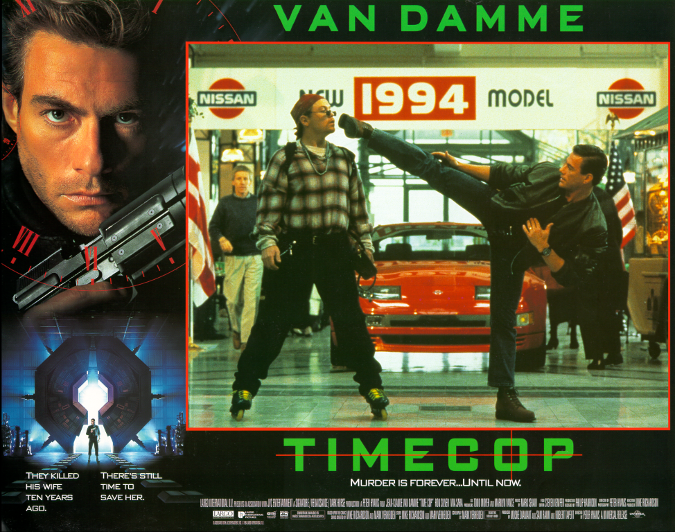
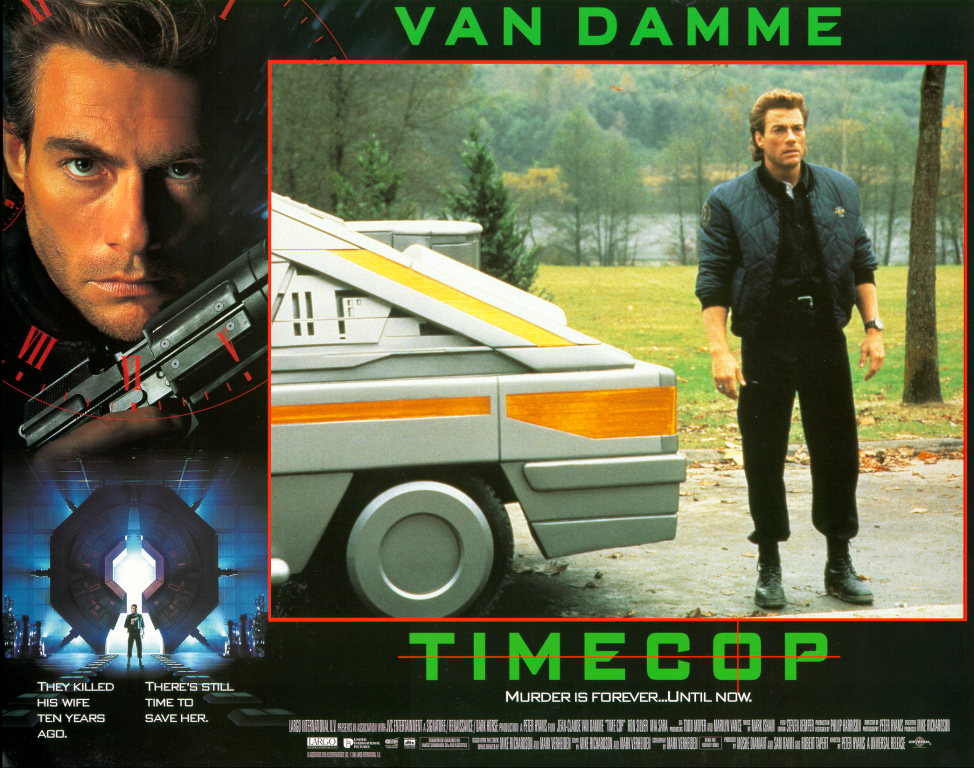
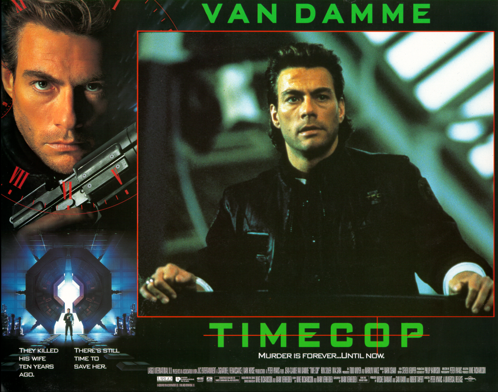
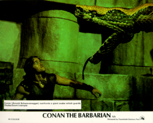
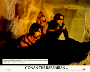
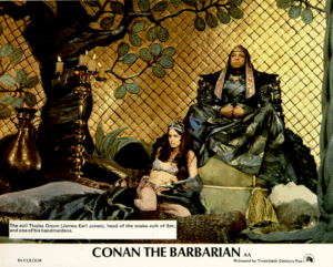
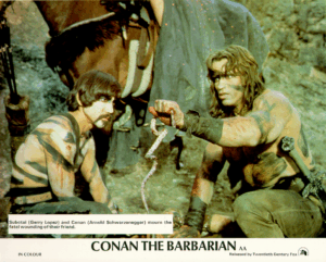
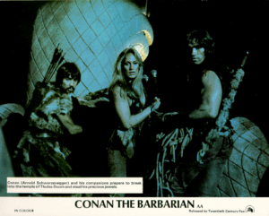
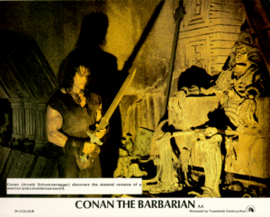
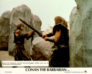
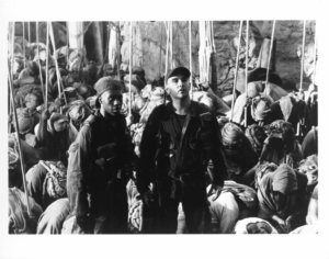
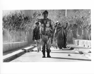
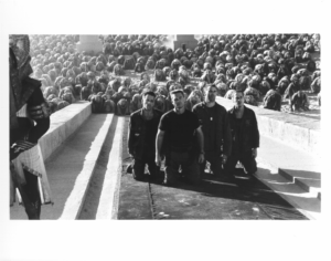
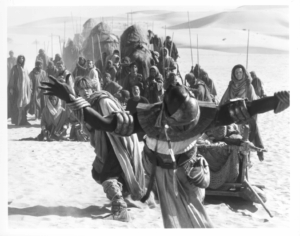
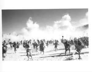
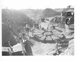
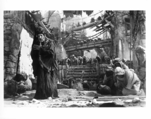
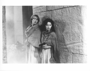
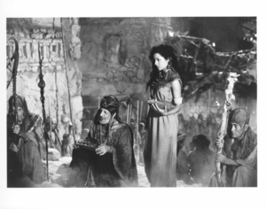
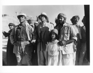
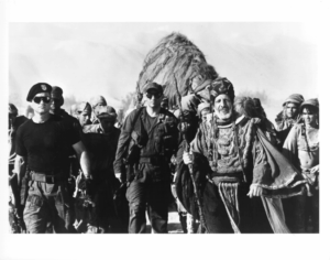
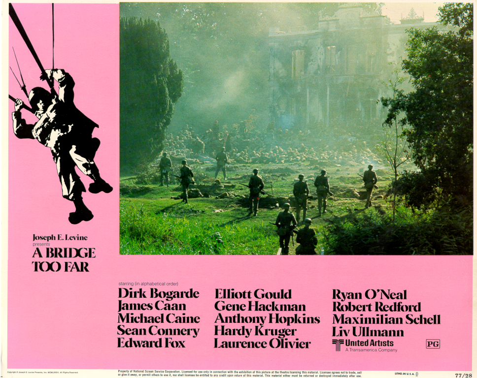
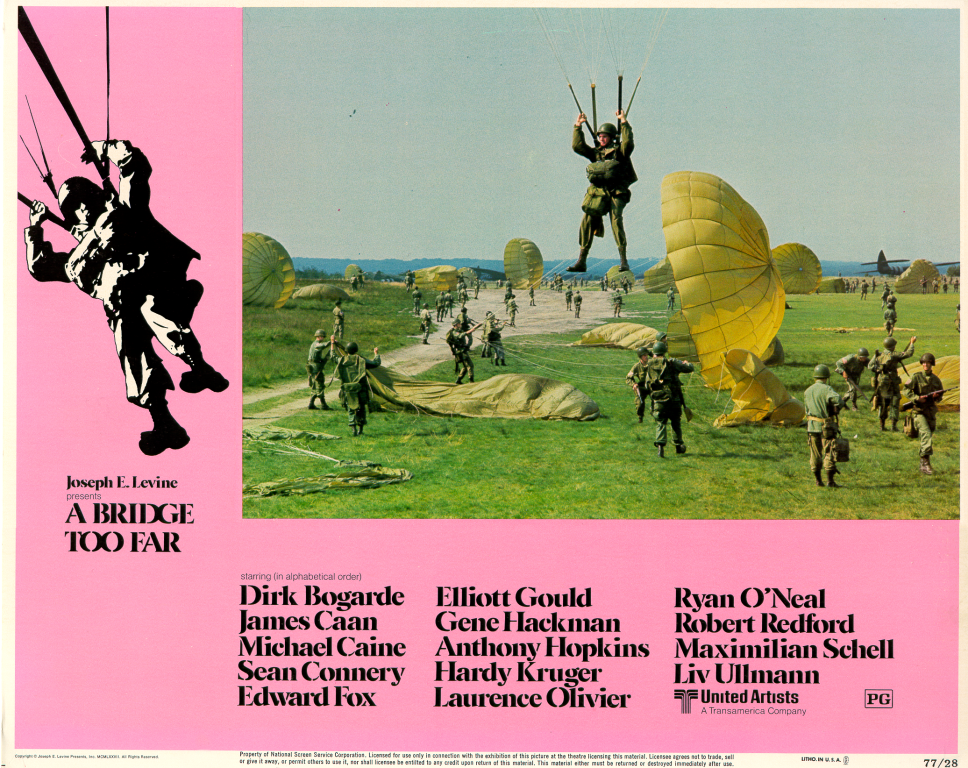
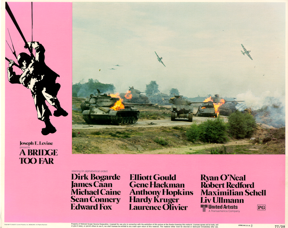
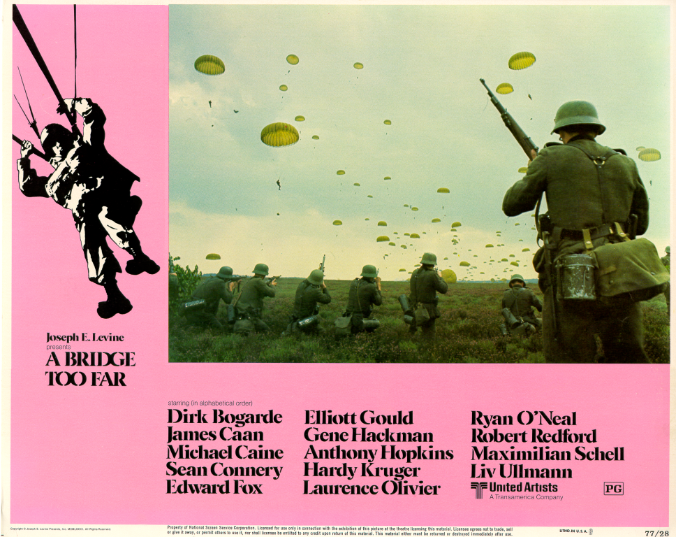
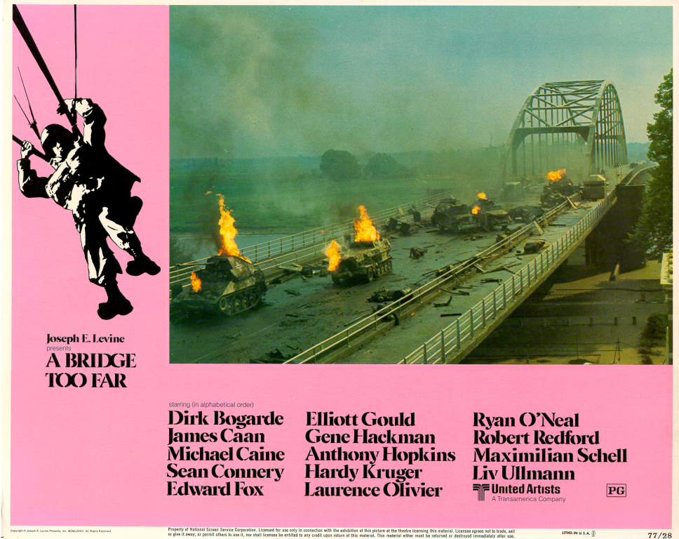
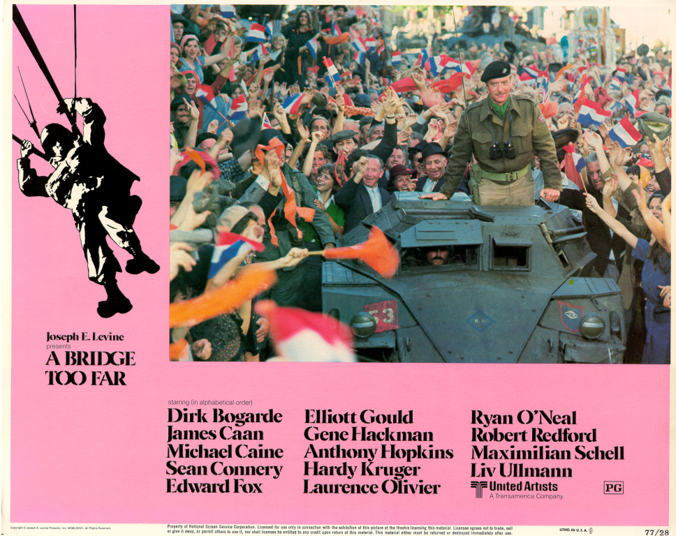
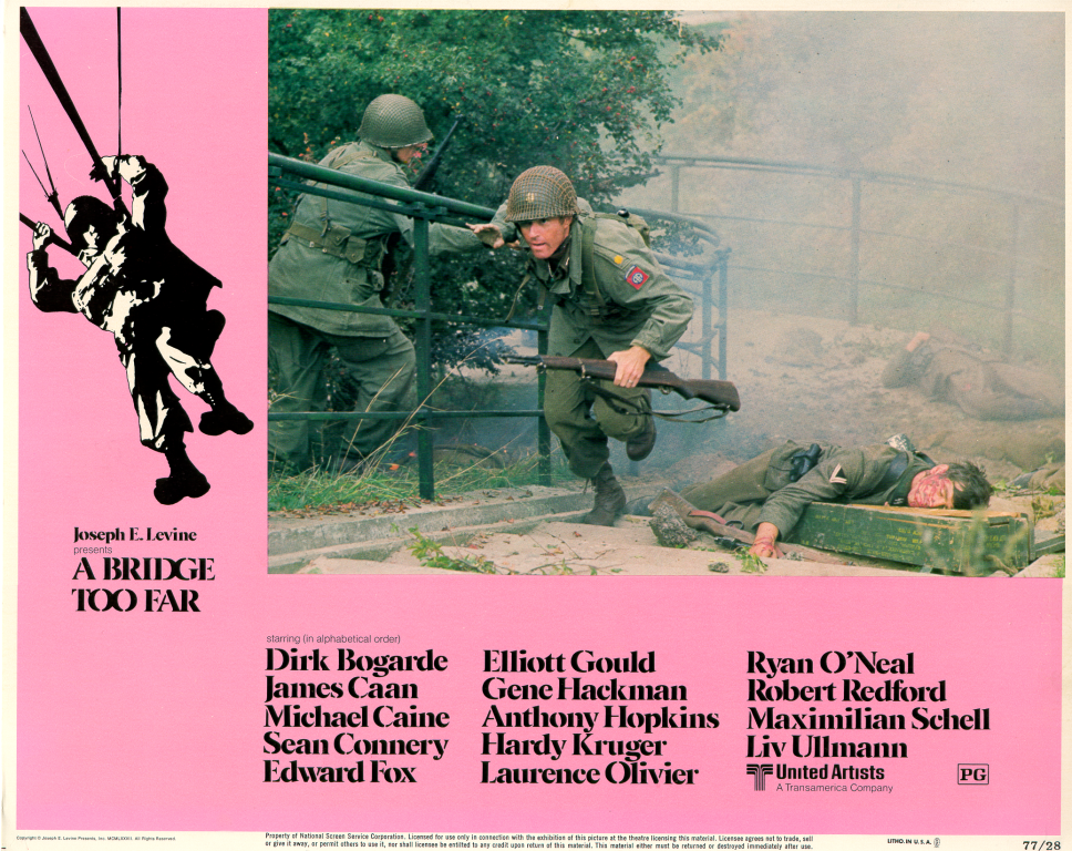
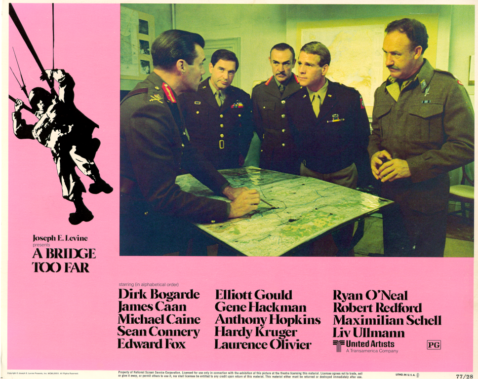
Some lobby cards from the movie with a cast of thousands.
There is nothing to see here at the moment.