What is the temperature outside now? In the pool? Inside the garden bed? How much light did we get today?
To answer these marginally useful questions the obvious solution is to build a solar powered, RF transmitting sensor – paired up with an RF receiver to act as an interface to the computer.
First thing some basic requirements
- Multiple temperature sensors
- Simple light sensor
- RF transmitter/receiver pair or transceivers
- Solar powered – implying battery powered
- Able to run 24×7
- Weather proof/resistent
Sourcing the Parts
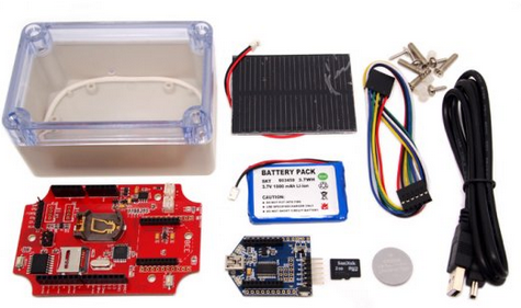
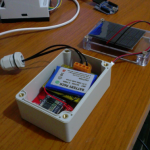
Again better not reinvent the wheel so after a few Google searches and numerous distractions I found the Seeeduino Stalker.
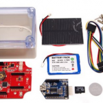
A nice starting point to get the main things I needed. In particular the Arduino board with solar input, lipo battery charger circuits, a cheap solar panel, a lipo battery and importantly a waterproof case ready to go.
I got a Bluetooth XBee module for quick testing as I already had a USB Bluetooth dongle so I could get something up and running pretty quickly without needed to prototype the receiver.
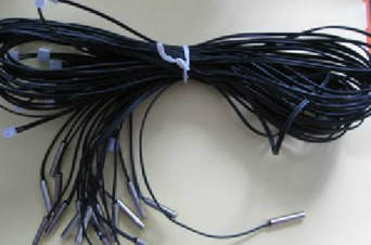
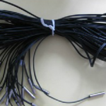
Now some cheap temperature sensors – Aliexpress has many options here. I went with some cheap 10K NTC resistor based items. I didn’t hold much hope about sticking these particular ones in the pool (salt water / chlorine) on inside the garden bed (moisture in general) but its a start and at the price they were cheap enough to be disposable.
The light sensor was just an LDR I already had in my parts draws.
Initial Setup and Results
I put some quick firmware together and as it was summer time with plenty of sun around I stuck with using Bluetooth as the communications put it all together and installed in by the pool with one temperature sensor dangling in the pool and the other just in free air.
Unfortunately I don’t have an image of the sensor that was in the pool – it lasted maybe a month before the temperature readings starting dropping – it appeared that the potting compound wasn’t really adhered to the wires and eventually the salt / chlorine / heat got into it – not unexpected.
The Bluetooth was marginal from the pool to the office – maybe 17 meters away and through a few walls and metal window shutters – not unexpected.
The battery recharging worked quite well – it was full Adelaide summer after all, weeks of 35+ degree days with no clouds. The graphs of battery voltage did indicate that the battery was pretty much marginal as is each night it almost expired only to be saved by the sun the next day.
Happy with the initial results none the less as I hadn’t done any power optimization at all.
Autumn Radio Upgrades
The initial prototype was retired after summer as the battery drain from the Arduino and Bluetooth modules running 24×7 was just too much. Plus the pool isn’t heated and there was little interest in the water temperature – you already know its cold. Naturally it was time for an upgrade.
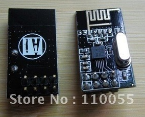
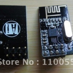
I have no idea how much power the Bluetooth module required as I didn’t measure it properly but my assumption of power usage and the range being quite poor I decided to upgrade the to some RF modules. An obvious and cheap choice was one of the numerous nRF24L01 modules you can source just about anywhere these days. $10 for 10 transceivers is very hard to beat so its worth a try.
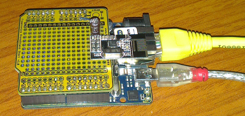
There are plenty of Arduino libraries out there for these modules so changing the code over was also pretty straight forward. I also needed to make a receiver in the office to get the data sent from the sensor.
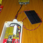
Here is the sensor at the bottom and receiver at the top as it is now.
It was now autumn and there was still enough sun during the day to keep things running overnight even though the Arduino was still running 24×7 at full speed (8Mhz). At this point I was already powering down the nRF module in between transmissions to save power.
Winter Firmware Upgrades
Winter comes along and the amount of sun during the day – assuming there is any at all – is just way too short. So time to finally get the firmware to do proper power management.
Lucky for me the Stalker board had an on board RTC. The firmware basically uses the RTC to set an interrupt/alarm every minute, wakes up, takes the readings, sends the message, and goes back to sleep.
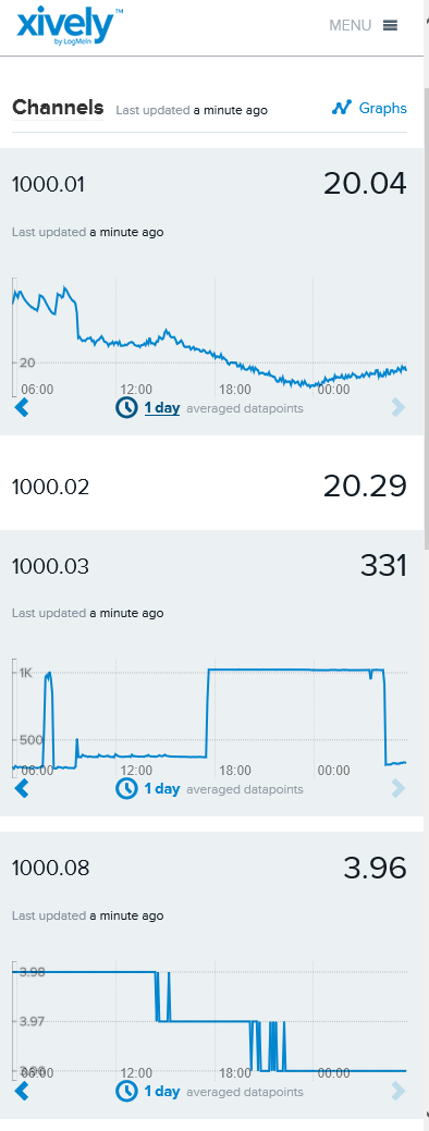
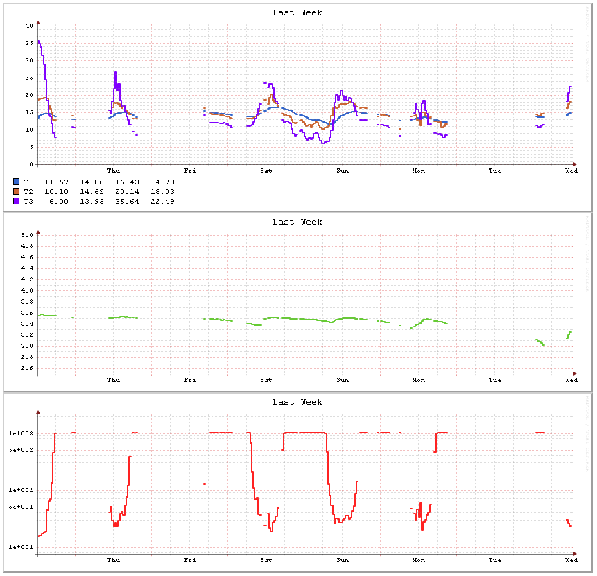
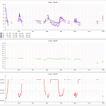
The results were much better – lasting over a week with little sun and the panel flat of the ground – less than ideal. Here is the graph for the last week.
Something Still Obviously Wrong
You will notice the graph is quite sparsely populated – to say the least. The sensor is pretty much outside my office window about 4 meters in the garden bed. The receiver is on my desk. At night the metal window shutters get closed and the sensor readings tend to disappear – not unexpected but annoying.
I think this is a problem with using the nRF modules, at least these ones with the PCB antenna. Some problems I have seen
- The angle at which I have the transmitter and receiver matters. Flat seems worse than upright.
- The range I get from the modules, while good, just isn’t good enough to reliably have communications from outside to inside, let alone from one side of the house to the other.
Future Upgrades
For now it will suffice but some future upgrades will include …
- Using a receiver with the nRF module that has the built in amplifier and normal antenna.
- Mounting the receiver on an outside wall to eliminate the metal window shutter problem.
- Using an POE powered + Ethernet enabled Arduino for the receiver and upload the data to a server rather than having the receiver connected to my desktop PC.
- Creating a few more sensors for around the yard
- Finding a solution for a pool water temperature sensor.
- Having the data available and graphed on a website so I can check whats happening from anywhere.
- Add a soil moisture sensor
- Add a humidity sensor
- Integration with my watering system