Information Displays – Part 1

As part of my home automation experiments I want a way to display the current state of sensors or currently active events on an LCD screen and install the LCD screen (or screens) in convenient locations round the house.

The basics requirements of what it should be able to do are as follows

  • Show a prioritized list of currently active events with columns such as priority code, message, elapsed time, etc.
  • Each priority should have configurable colors (foreground/background/flash), sound (file, repeat)
  • Show the current date and time
  • Show some basic status of the application (offline, online, etc) in case a connection to the server is not available.
  • Show the current value of sensor/value type points (temperature, humidity etc)
  • Configurable background image(s)
  • Be able to run in full screen mode (i.e when installed on the wall) or window mode (easier for development or running on the desktop)
  • Be able to auto start the application when the machine boots up if required.

Nice to haves

  • Full screen mode – try to blank the screen when no-one is in the room?
  • Perhaps go silent when no-one is at home?

More things I’m sure, but can’t think of anything else at the moment.

Initial Use Case

The initial use case is to display a message and play a doorbell like sound when my doorbell is pressed.

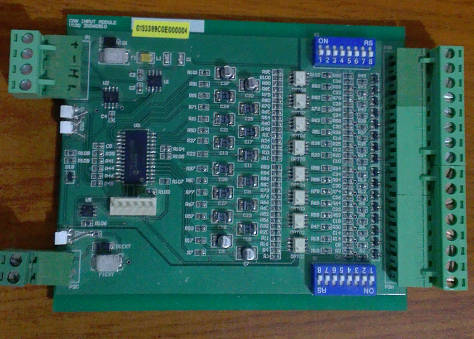
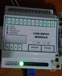
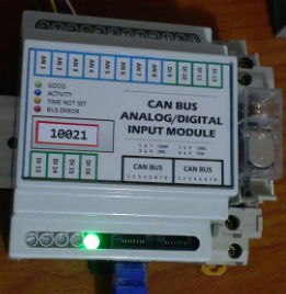
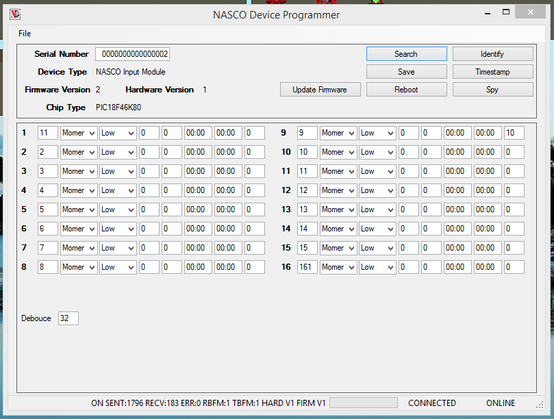
For reference my front door bell is a wired switch connected to an input module. The input is configured as a momentary input, with a 10 second timer (see input #9 in the screen shot). When pressed the event makes its way to the server for other applications to see.

 CAN Input Module Setup

Implementation

It sounds possible to implement this in a web browser but being lazy I cant be bothered to learn the latest html5, json, web socket, bootstrap, blah, blah, blah technologies … so initially I go with what I know best and implement this as a .NET application and leave a web version for another time (i.e. probably never) 🙂

Endless Revisions

I find when I’m coming up with my own hardware designs there’s always something else that would be nice to have, could be better,  or just different. Most likely it comes from having no fixed set of requirements up front. Perhaps the exact end application isn’t exactly known ahead of time as sometimes happens when trying to design generic items.

To this end I present the endless revisions of … the CAN input module .. over 7 years (yay for date codes on the PCB silk screens)

2006-05 CAN bus, 16 isolated digital inputs, DIP switch pull ups for each input, hardware debounce, unique ID chip, large aluminium enclosure, large 5mm plug and socket connectors. This version I threw everything in but its just too big and the cost was just too much mainly due to the enclosure but also the number of connectors. I never got around to doing the PCB end plates.

input-module-a

2006-11 CAN bus, RS485 bus, 8 non-isolated digital inputs, 8 open collector digital outputs, unique ID chip, small plastic enclosure, large plug and socket connectors. I think this one was modelled of the popular ADAM4050 module from Advantech. Simplify everything and reduce cost. It’s almost 1/4 of the size of the previous module and much less parts. Still just having the plastic case makes it ugly to install anywhere and look nice. Again I never got around to doing the PCB end plates.

input-module-b

2012-10 CAN bus, 16 non-isolated digital inputs, DIN rail plastic enclosure, screw terminals for inputs and RJ45 for CAN bus. Skip forward few years, I guess sometimes you never get a project “quite right” and you just have to do another revision. This one got most things correct in my mind. Cheap to make, single purpose by removing the outputs, nice to install on a DIN rail and standard CAT5 for bus interconnect and power. The case has a nice recess for the label for all the relevant installation details which is handy.

input-module-c

… but there is always something else … I was writing the firmware and saw that I could use 8 of the inputs as digital or analog inputs – so another revision …

2013-04 CAN bus, 16 non-isolated inputs, the first 8 can be optionally configured as analog inputs, internal pull up or pull down jumper for the analog inputs, DIN rail plastic enclosure, screw terminals for inputs and RJ45 for CAN bus.

input-module-d

Its 2014 and surprisingly I can’t think of anything to add feature wise, but that doesn’t mean there isn’t something else … that can be a topic for another post.