A (long) while ago I did a post on some touch light switches I acquired. The single button one is still running in the office with no problems. I figured I’d have a go at trying to get the 4 button one to work without mains.
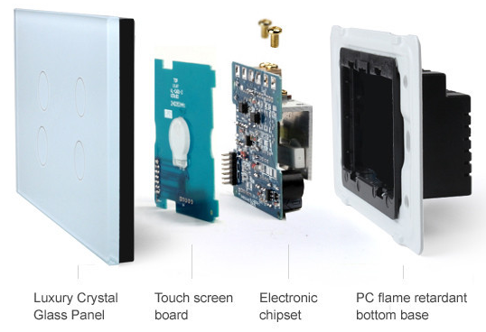
The switch has
- a glass front plate
- a top PCB with the PIC, LEDs and touch pads
- a base PCB with the relays and mains terminals
I took it apart to get the top PCB. It has a clear silkscreen with vias labeled with 3V and 12V. The 3V via went to the VDD pin of the PC, so seems like it runs off 3V provided by the base PCB. Knowing the PIC pin out gives us a GND point on what looks like a programming header.
I traced/buzzed out 4 of the other header pins that control the relays.
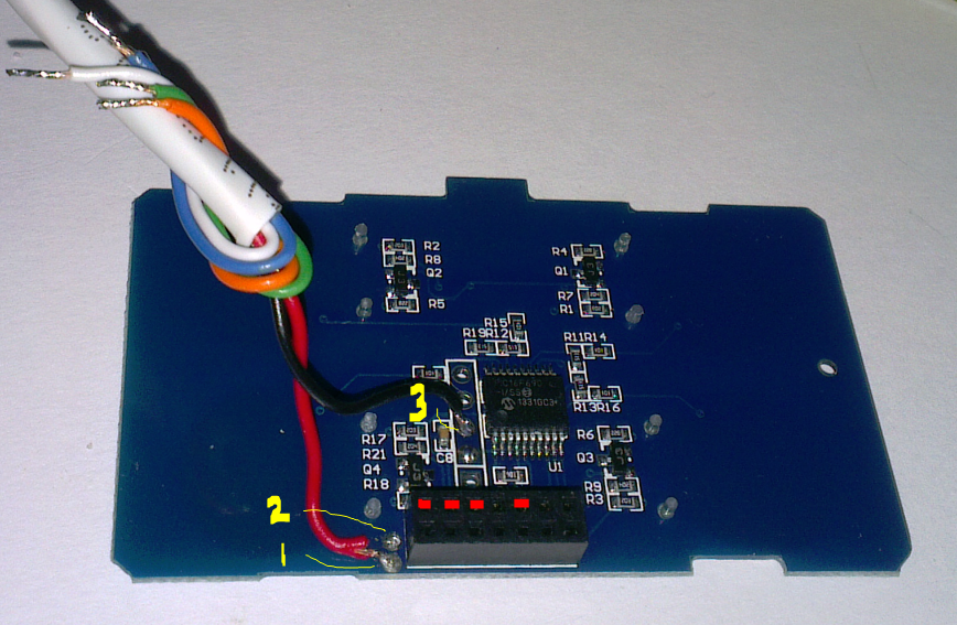
(1) is the 3V point, (2) is tht 12V point, (3) is GND, The red dots are the control lines for the 4 relays.
First Test
First test is just to apply 3V and GND to the top PCB only – if it works I can just supply power and take the control lines for the relays to my input modules.
So it powered up, but immediately went into a sequence of alternately red/blue LED every 2 seconds. Oh well not much use, but worth a try,
Second Test
Maybe it needs the 12V for something? This time I applied 12V and GND, connected the top and bottom boards together and powered up.
Again it powers up, the 3V rail is generated and the PIC once again works. However the same 2 second sequence occurs, this time with the relays also changing state in time with the LEDs.
Other Tests
Maybe it needs the glass plate installed to calibrate the touch sensors? nope – powered up with it assembled and still the same sequence.
So what to do next. I will reassemble everything and plug it into the mains just to be sure it actually works as expected – maybe its a dud?
If it works with the mains then at least I know its still a function unit and more hacking/testing is needed to run it on my 12V bus.